DoublePlay Installation Guide
About Pixellot
Pixellot offers automated sports production solutions that provide affordable alternatives to traditional video capture, production, and distribution systems for professional and semi-professional sports events. Founded in 2013, Pixellot’s AI technology solution streamlines production workflow by deploying an unmanned multicamera system in a fixed location, with additional angles as required, to cover the entire field, offering a stitched panoramic image. Advanced algorithms enable automatic coverage of the flow of play and generate highlights. Pixellot systems are deployed by broadcasters, production companies, clubs, federations, universities, high schools, sports portals, and coaching solution providers around the globe.
For more information visit: www.pixellot.tv
Legal Notice
This document contains proprietary and confidential material of Pixellot Ltd. Any unauthorized reproduction, use, or disclosure of this material, or any part thereof, is strictly prohibited. This document is solely for the use of Pixellot employees and authorized Pixellot customers.
The material furnished in this document is believed to be accurate and reliable. However, no responsibility is assumed by Pixellot Ltd. for the use of this document or any material included herein. Pixellot Ltd. reserves the right to make changes to this document or any material included herein at any time and without notice.
For more information visit: www.pixellot.tv
Copyright © 2022 Pixellot Ltd.
All Rights Reserved.
1.0 Introduction
1.1 System Features
· Fixed Installation: Indoors or outdoors, weatherproof
· Unmanned capture: Panoramic field capture in 8 Megapixel resolution
· Automated production: Auto-tracking algorithms follow the flow of play and produce TV-like footage
· Distributed to any device: Streamed in HD quality to mobile devices and web platforms
· Personalized viewing experience: Zoom into any scene, replay, clip and share
1.2 Easy Installation
Pixellot Multi Angle Baseball is weatherproof and suitable for installation at any sports arena, both indoor and outdoor. The system is easily installed by any experienced technician who has been trained in the installation process. Some minor infrastructure preparations may be required prior to the system installation. Once installed, the system is maintenance free and can be fully programmed and managed remotely. This manual describes the procedures for installing the system at a fixed location.
For additional information and/or consultation go to https://helpdesk.pixellot.tv.

1.2.1 DoublePlay (Multi-Angle) Baseball System Schematic Diagram
The following schematic diagram shows the setup of the Multi Angle Baseball system.
2.0 Safety Instructions
- Read this user manual carefully before operating the system.
- Follow the authorized maintenance and repair procedures recommended by the manufacturer.
- Do not open the unit as this may void the warranty.
- Installation should be done by an experienced technician who has been trained for Pixellot installation.
- Ensure that all electrical connections are properly grounded.
- Ensure that all components and cables are installed in a manner that does not pose a threat of tripping, collision etc. to the players and/or spectators.
3.0 System Components
3.1 Overview
The primary components of the Pixellot Multi Angl e Baseball system, which must be installed at the sports venue, are the Camera Head Unit (CHU) and the Video Processing Unit (VPU).
The customer should provide the cables needed to connect the CHU to the VPU as well as all connectors and infrastructure elements needed for the cable connections.
3.1.1 Required Equipment
Make sure you have received the following:
· Camera Head Unit (CHU) - DoublePlay
· Visual Processing unit (VPU) or Computer
Front View Back View
· Additional angle camera (AA)
3.2 Document Scope
This document describes the installation of the S2S and AA (Additional Angle) units in a baseball environment.
3.3 Main Components
3.3.1 Camera Head Unit (CHU)
The CHU is the specially designed Pixellot camera unit which captures a panoramic view of the action on the court/field. The S2S CHU consists of two wide angle cameras that combine to provide up to 180° video coverage. The alignment of the cameras is adjustable, enabling you to optimize the positioning of the cameras for your deployment location. The video feed is delivered to the VPU through two cables that are attached to ports on the bottom of the CHU.
- Cameras – Each camera captures wide angle video at up to 8 MP resolution
- Mics – The CHU contains two microphones to capture the ambient sound.
- Mode Selection Pin/Mode Selection Groove – The alignment of the cameras can be optimized by adjusting the Mode (i.e. the angle at which the two cameras are aligned). This is done by positioning the Mode Selection Pin in the proper Mode Selection Groove. (See Cable Configuration.
- You need to determine the path through which the cables will pass in order to connect the CHU to the VPU.
- You will also need to determine how the cables will be terminated and what additional components and parts will be needed to complete the cable connections.
Choosing the Cable Route
Choose the route using the following guidelines:
· Ensure that the cables and their conduits do not obstruct movement of players or spectators.
Measuring the Cable Length
Measure the total length of cable needed to cover the route from the CHU to the VPU and record it. If the cable length is greater than 100 m then you will need to use the Extended Range Kit. If it is greater than 200 m then you will need to use two Extended Range Kits.
Required Components
Determine how the cables will terminate (connectors, outlets) and what additional components and parts will be required.
CHU Front View
3.3.2 Additional Angle Camera (AA)
The AA is part of Pixellot’s multi angle configuration, which is unique to the baseball setup. Its primary aim is to enable capture of multiple viewpoints.
AA Front View
The Additional Angle camera comes with customized housing and a mounting arm.
After housing the AA camera in the protective housing unit, position it on a pole adjacent to the main CHU to capture the action from the other side.
3.3.3 Video Processing Unit (VPU)
The VPU is the workstation that processes the video data that is input from the CHU. The VPU stitches the video from both cameras into a single panoramic view. Then, it applies Pixellot's patented AI auto-tracking algorithms to produce a professional quality broadcast of the sports event for cloud-based distribution to mobile devices and web platforms. The VPU is set up in a secure location at the sports venue, where it is connected by two ethernet cables to the CHU. During the installation process, you will need to connect a monitor, keyboard and mouse to the VPU to set up the initial configuration and internet connection.
· AC Power – an AC power adapter plugs into a standard AC outlet.
· Ethernet Ports – can be used to connect to the Internet.
· USB3 Ports – The USB cable from the Audio Interface is connected to a USB3 port on the VPU.
· PoE Ports – the Cat6a STP cables from the CHU connect to these four ports, receiving video input and providing power to the CHU.
· 2 X Bayonet Connector Casings – Casings for the male segment of the bayonet connectors. These casings are attached to the RJ45 connectors to prepare them for insertion into the CHU.
Front View Back View
4.0 Installing the Cameras
4.1 Installing the CHU
4.1.1 Configuring the CHU Junction Box
1. Open the CHU Junction box by turning the four bolts on the corners.
2. Remove the middle strip gland from the box.
3. Using a screwdriver, open the strip gland, using the teeth to lift it from both sides, so the gland splits into two parts, and the grommets can be removed safely.
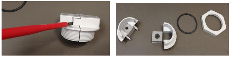
4. Tighten the gland to the box using the white nut. (Make sure the sealing ring is attached to the gland).
5. Connect the ethernet cable to the camera’s black female connector in the box.
6. Close the box and test the system before proceeding with the installation.
4.1.2 Installing the CHU on a Wall or Pole
1. Use the four holes to on the base to attach the mounting screws directly onto a wall.
2. Alternatively, you can install the CHU onto a pole using steel bands.
3. Release the bands and thread them through the mount holes.
4. Circle the pole with the bands and tighten until the mount is secured to the pole.
The CHU is now attached in place.
4.2 Installing the AA (Additional Angle Camera)
4.2.1 Installing the AA (Additional Angle) camera on a pole or wall
2. The AA system is comprised of multiple parts: the camera, mounting plate, spit glands, gromets, ethernet cable, cooling fan and washers. (see image below)
3. Attach the ¼” bolt adapter to the camera using 2 screws.
4. Position the camera plate on the AA camera and secure it using a ¼“ screw. Make sure that you position the plate in a way that enables access for a screwdriver.
5. Remove the fan from the housing unit.
6. Thread the ethernet cable through the spit gland by opening it and returning it to place.
7. Disassemble the split gland:
a. Using a screwdriver, gently lift the gland’s teeth from both sides so that it splits into two parts.
b. Remove the gromets.
c. Thread the cable through the spit glands and then re-attach them.
d. Reattach the fan to the housing unit.
8. In order to properly position the camera, mark the location of each screw using a marker and place the camera at the desired position.
9. Unscrew the camera from the plate.
10. Position the plate on the black screw marks and mark the position for the front screws.
11. Screw in the front screws leaving enough space for the plate to be inserted.
12. Reattach the plate to the camera.
13. Position the plate onto the screws and slide it back to secure it in place.
14. Tighten the back screws (as shown below) and verify that the plate is secured in place.
15. Connect the ethernet cable to the camera and close the housing unit.
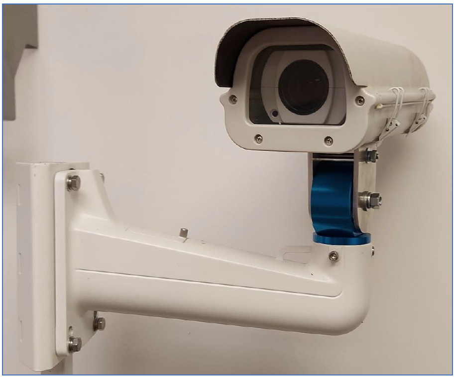
16. Attach the U-shaped aluminum bracket to the bottom of the housing unit, using two ¼” x ½” screws and two flat spring washers.
17. Place the blue mounting bracket onto the mount’s arm, adjust the pan, and tighten the screws on both sides.
18. Secure the camera on the arm mount using 2 bolts:
a. 3/8” for the ax (the bottom part)
19. Tighten all screws after positioning the camera in the correct angle. (ax)
20. Locate a suitable wall or pole adjacent to the CHU camera with a clear and unobstructed view of the field. The recommended position for the Additional Angle camera is behind the pitcher, on a static wall or pole.
21. Attach the AA unit to the top of the pole or wall using steel bands or screws.
22. If using bands, release the bands and thread them through the mount holes.
23. Circle the pole with the bands and tighten until the mount is secured to the pole.
24. The AA is now attached in place.
25. Connect the AA directly to the VPU using a LAN cat6A and a cable.
26. If the distance between the AA and the VPU is over 100m, use a repeater.
4.2.2 Installing the Cables

• Ensure that the cables and their conduits do not obstruct movement of players or spectators.• If the cables run along the floor/ground, make sure that they are below ground or flush with the ground so that they don't pose a tripping hazard.
• If you are using a junction box/s (required for outdoor installation) use the following procedure:1. Attach the junction box to a pole or wall within 2 meters of the CHU.2. If you are using repeater units (required for long range installation), install a junction box housing the repeater units at intervals of no more than 100 m (328' 1").
1. Remove all parts from the plastic bag and lay them out on a clean work surface.
2. Make sure that the RJ45 male connectors don't have any protruding moldings (aside from the connector pins) as this will interfere with the insertion of the cable into the bayonet casings.
3. If the connectors do have a protruding molding, you may be able to strip it with a utility knife. Otherwise, the connector will need to be replaced.4. Attach all washers and casing parts to the cable in the order shown below (as shown in the instructions included in the bayonet connectors package).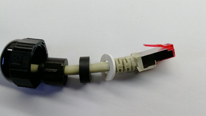 5. Push the end of the connector through the bayonet casing with the pin aligned with the channel in the casing. Push it through fully until you hear a 'click'.
If the cable is not properly inserted into the bayonet casing then the connection with the CHU will not be effective.6. Perform the identical procedure on the second cable.
Don't attach the cables to the CHU until the CHU has been mounted in it's final position.
5.0 Installing the DoublePlay - Multi-angle system
1. Download the Pixellot Connect app.
QR Code for Downloading Pixellot Connect App:
2. Follow the instructions to complete the installation.
3. If you encounter any issues or have any questions contact Pixellot support at: helpdesk.pixellot.tv
Related Articles
S2S Installation Guide
About Pixellot Pixellot offers automated sports production solutions that provide affordable alternatives to traditional video capture, production, and distribution systems for professional and semi-professional sports events. Founded in 2013, ...Installation Guide
About Pixellot Pixellot offers automated sports production solutions that provide affordable alternatives to traditional video capture, production, and distribution systems for professional and semi-professional sports events. Founded in 2013, ...Fiber Kit Installation guide
About Pixellot Pixellot offers automated sports production solutions that provide affordable alternatives to traditional video capture, production, and distribution systems for professional and semi-professional sports events. Founded in 2013, ...S2 Installation Guide
About Pixellot Pixellot offers automated sports production solutions that provide affordable alternatives to traditional video capture, production, and distribution systems for professional and semi-professional sports events. Founded in 2013, ...S3 Installation
1.0 Introduction - S3 Installation Pixellot S3 offers automated production of sports videos. Based on Pixellot's patented, fully automated end to end production workflow, Pixellot S3 generates and delivers TV-like footage without a person in the ...